Introduction to Dynamic Positioning
5 - DP Operations
5.1 - Diving and ROV Support Operations
Many DP vessels are designed specifically for supporting divers (DP DSVs). Other vessels have a multi-role function, including diver support. The variety of work that may be conducted by a diver is almost endless: carrying out inspection or survey work, installation and configuration of equipment, monitoring of an operation, or recovery of lost or abandoned equipment. Much of the work hitherto conducted by diver is increasingly carried out by ROVs (remotely operated vehicles - unmanned submersible vehicles) but there are still tasks which cannot be completed remotely, and which require human intervention.
There are different types of underwater operations. 'Air range' diving is limited to a depth of 50m. The technique is so called because the diver's breathing gas is compressed air.
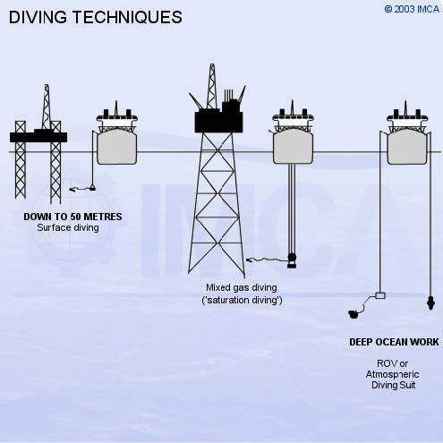
Sketch 5.1 - Diving techniques
The hazards of diving from vessels with rotating thrusters and propellers are obvious. One vital requirement of any diving set-up, from a DP vessel, is that the amount of umbilical the diver may be given, measured from the tending point (basket or bell) must be at least 5m less than the distance to the nearest thruster. This is to ensure that the diver cannot be drawn into a thruster or propeller. This can be broadly illustrated by the sketch below.
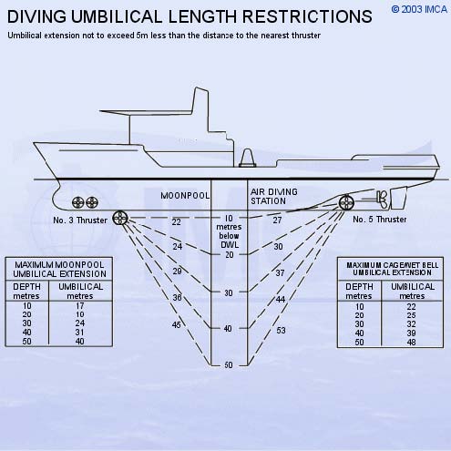
Sketch 5.2 - Umbilical length restrictions
Below 50m the diver must be deployed from a diving bell and his breathing gas is a helium/oxygen mix (Heliox). The diving bell maintains the diver at the pressure of the working depth, and mates with a hyperbaric complex on board the vessel. The divers live in this hyperbaric chamber, also maintained at pressure, for up to 28 days, travelling "to work" in the diving bell. This technique is known as "saturation diving". The bell is usually deployed through the moonpool, an open well in the centre of the vessel. A typical "bell run" would consist of three divers (two swimmers and a bell-man) operating for an eight hour shift. The swimmers are provided with all gas, hot water for heating, and communications through umbilicals connected to the bell and ultimately to the vessel.
At present the practical limit for bell diving is about 300m. At greater depths than this, the work must be done by deep-water ROV or a diver in an atmospheric diving suit (ADS) must do the work. ROVs or unmanned submersibles are increasingly sophisticated units able to operate a wide variety of tooling, sensors and other instrumentation.
5.2 - Survey and ROV Support
Support vessels of this type may perform a multitude of tasks from hydrographic survey, wreck investigation, underwater recovery, site survey, installation inspection and maintenance. Although the task itself may be relatively non-hazardous, the location itself may have hazards, especially if in close proximity to a platform structure.
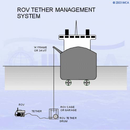
Sketch 5.3 - ROV Tether Management System (TMS)
An ROV may be deployed direct from a gantry or ‘A’ frame at the side or stern of the vessel, or from a tether management system (TMS) incorporating a cage or garage. If deployment is directly overside then great care must be taken to ensure that the umbilical does not foul the thrusters or propellers. The DP control system of the support vessel can be put into a ‘follow sub’ or ‘follow target’ mode for this work, where the acoustic transponder on the vehicle becomes the position reference.

Sketch 5.4 - Follow Target
5.3 - Seabed Tractors and Trenchers
A seabed tractor or trencher may be configured to lay and bury a cable. These vehicles are tracked crawlers, built to be controlled from the vessel, with operators ‘driving’ the unit as if they were on board. These units usually move slowly, depending on soil conditions. In some cases an ROV is deployed independently, to record progress and performance.
Trenchers for pipeline burial are much larger and heavier. The trencher is lowered onto the seabed over the pipeline and the DP control system can set the centre-of-rotation of the trencher.

Sketch 5.5 - trenching operation
5.4 - Pipelay Operations
Many pipelay operations are conducted by DP lay barges.

Sketch 5.6 - Pipelay methods
In a typical S-lay barge, the pipe is constructed in a linear pipe fabrication facility called the "Firing Line" in which a number of stages of welding take place. Each operation is conducted at a "station". Further stations conduct X-ray and NDT testing on the welded joints, anti-corrosion coating, and weight-coating if necessary. At intervals, the DPO initiates a move ahead a distance equivalent to the joint-length. Once the move ahead has been completed, the firing-line operations continue.
It is essential that tension is maintained on the pipeline. At the back end of the firing line, the pipe is held by a number of pipe tensioners, or caterpillar tracks clamping the pipe. The tensioners control the movement of the pipe, maintaining a set tension on the pipe string. The pipe is supported aft of the firing line by the "stinger", which is an open lattice gantry extending beyond the stern of the vessel, sloping downwards. Tension on the pipe is needed to prevent pipe damage from buckling. The set tension is to ensure a smooth catenary to the touchdown point on the seabed. If tension is lost, then damage will occur at the touchdown area.
Pipe tension values are communicated to the DP system which is continually providing thrust commands to maintain tension, position and heading.
Pipelay operations are particularly dependent upon environmental conditions. The vessel must be able to cope effectively with the tides, sea state and wind conditions from most directions, because it is not possible to allow the vessel to weathervane.
5.4.1 - J-Lay Operations
In deeper water, S-lay is not feasible and J-lay is common. In J-lay operations, the stinger is configured as a tower, angled between the vertical, and up to 20 degrees from the vertical. Pipe lengths are pre-jointed into triple or quadruple joints before being raised to the vertical for welding onto the pipestring.
5.4.2 - Reel-Lay Operations
This type of operation varies from those described in that the pipestring is prefabricated in one length at a shore-based factory. The vessel loads the pipeline straight from the factory, spooling it onto a reel or into a carousel. The vessel can transit to site with the pipe to lay it by feeding it off the reel/carousel via straighteners and tensioners, either singly or as a bundle.
5.5 - Rock Dumping Operations
Rock dumping vessels have DP systems for accurately dumping rock on the seabed for a variety of reasons. They range from mini-bulk carriers, able to carry out burial operations using fallpipes, to smaller deck-loading vessels mainly used for erosion rectification projects. All of these vessels that work in the offshore industry are fitted with DP systems, because good track speed control, and hence uniform, economic rock distribution, is possible.
The commonest need for rock dumping is to provide protection to untrenched pipelines.
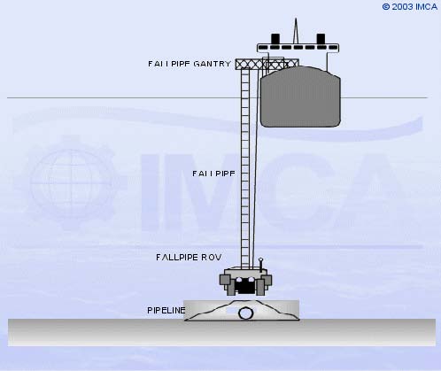
Sketch 5.7 - rockdumping
A commonly used feature is the ‘auto-track’ function of the DP control system, which enables the vessel to track accurately along a line defined from the preset waypoints of an earlier pipeline survey.
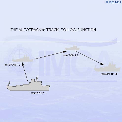
Sketch 5.8 - Autotrack or Track Follow
This type of vessel is also used to provide protection against tidal scour or erosion, which occurs in high tidal stream areas. The sediment around the legs of a Jack-up drilling rig, for example, can become eroded to the point where the rig becomes unstable.
5.6 - Dredging Operations
Most new dredgers now have a DP capability, because they wish to move along parallel tracks. For the trailing suction dredger, for example, the tracks must be close together with minimum overlap. This is ideal for ‘track follow’ abilities of the DP control system.
Vessels dredging for aggregates can require precise positioning to ensure they are dredging in licensed areas and to assist with locating particular types of material.
5.7 - Cable Lay and Repair Operations
Modern fibre-optic cables are more fragile than traditional cables, so they have more limitations on loadings and bend radii. Thus it is now common to use DP vessels for cable lay and repair.

Sketch 5.9 - Cable lay methods
For cable lay operations within coastal waters or other shallow-water areas, it is often necessary to bury the cable in order to prevent damage from fishing gear. When a plough is used, it is towed by the ship, in a similar manner to a tractor towing an agricultural plough across a field. This reduces the power available for station keeping.
The phase of the operation where the DP capability proves most useful is the shore-end tie-in. This is where the vessel comes to the end of the lay, a short distance from "the beach", to complete the connection. This involves the vessel keeping a fixed location, close to the shore, in shallow water, where strong tides may also stream.
5.8 - Crane Barge Operations
Crane barges are employed all over the world in construction and de-commissioning operations relating to the oil and gas industries, and also in civil construction projects. They are also used in salvage and wreck removal operations.
Many crane barge and construction vessels are DP-capable - the larger ones generally to IMO equipment Class 3. The major advantage of DP to these vessels is the ability to complete a task in a very short time span, because the time needed to lay and recover moorings is saved, as is the risk of the moorings damaging nearby pipelines and structures.
5.9 - Mobile Offshore Drilling Units (MODUs)
Deepwater developments offshore in the Gulf of Mexico, offshore Brazil, West Africa and the UK West of Shetland have made DP the only real option, as moorings are depth-limited. Even in shallower waters, DP is increasingly used for the positioning of drilling rigs while anchors are run. A DP rig or drillship may locate onto the worksite and commence drilling earlier than a similar rig using anchors. This is an advantage, particularly when only one or two wells are being drilled.
5.9.1 - DP Drilling Operations
The centre of rotation used by the DP control system is the centre of the drill floor rotary table, which for both monohulls or semi-submersible rigs is usually in the centre of the vessel.
For drilling operations, it is important for the vessel to keep over the well, such that the riser connecting the vessel to the well is practically vertical. The profile of the riser is, however, determined by current forces and tension, as well as by vessel position. The parameter that is continuously monitored is the lower main riser angle. If this exceeds 3°, action needs to be taken so that it does not get worse and force an unwanted disconnection.
For each well or location, the rig will have well-specific operational guidelines (WSOG), which determine when alerts are to be given and what action is appropriate. Watch circles might be used and set which are distances that represent angles at the lower end of the riser.

Sketch 5.10 - Deepwater drilling - the Riser Angle Mode
Some DP control systems have a function known as ‘riser angle mode’. When selected, the DP continues with a geographical position reference, but moves to reduce the riser angle. The reference for positioning is the angle of the riser at the stack, using sensors attached to the riser and the lower marine riser package (LMRP). These sensors may be electrical inclinometers, hard-wired to the rig up the riser or a Differential Inclinometer Transponder assembly, sending angular and positional information acoustically via the HPR system interfaced to the DP.
The DP system aboard the rig will have special display pages showing Riser angle offsets as part of a Position Plot display page.
DP rigs are currently configured to operate in water depths of up to 3000m. In these water depths the most reliable form of position reference is DGPS. Two or three separate and distinct DGPS systems provide redundancy, provided that different differential correction links are used. Further position-reference is obtained via deep water Long Baseline acoustic systems.
5.10 - Offtake Tanker and FPSO Operations
Tankers intended to load at Offshore Loading Terminals (OLTs) will be fitted with systems very similar to those in any other DP-capable vessel, but configured specifically for the offshore loading function.
The installations which support offtake tanker operations vary from field to field. Typical installations are Spar buoys, which are large floating tower structures moored by a spread of mooring lines. Spar buoys usually carry a rotating turntable at the top to handle vessel moorings and hose handling equipment.

Sketch 5.11 - OLT configurations
A UKOLS facility has a loading hose connected to a mid-water buoy. The buoy is positively buoyant and is moored at a fixed depth, above a gravity-based housing or pipeline end manifold (PLEM). Vessels using this facility have no need for a mooring hawser; the only connection to the buoy is the hose. A more recent development is the submerged turret loading (STL) system, where the loading connections are located in a subsea buoy. The buoy is moored above the PLEM at a depth greater than the draught of the offtake vessel. The STL is mated into a docking port built into the forebody of the vessel, and carries the flowline connections to the vessel. Once locked into position, the vessel is able to weathervane using the swivel through the centre of the STL. A development of the STL is used for production.
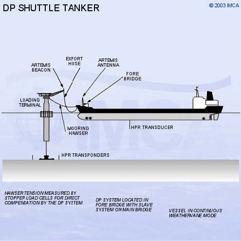
Sketch 5.12 - Shuttle tanker
5.11 - FPSO Unit Operation
Floating Production, Storage and Offtake units are becoming common in many parts of the world. Many FPSOs are able to weathervane around the turret and maintain heading into the weather.

Sketch 5.13 - FPSO/shuttle tanker offtake arrangement
Most FPSOs utilise offtake tankers for export of oil, and these tankers are usually DP-capable. With any FPSO/offtake tanker operation, the tanker will experience more positioning problems than when loading from an ALP. The offtake vessel keeps position within a circle defined by the length of the loading hose. The reference position is the hose terminal point on the stern of the FPSO. The mooring and positioning system in the FPSO allows a degree of movement, especially in deep water, so the FPSO may be continually weathervaning, so that the shuttle tanker reference point will be moving. The shuttle tanker can try to follow this movement or position absolutely to pre-set limits.
In FPSO offtake operations, a relative position reference is essential. One such position reference is the relative GPS (DARPS) system, yielding position information reduced to range/bearing data from the FPSO terminal location. Another position reference is Artemis, with the fixed station located on the FPSO and the mobile station located on the tanker. The prime consideration is the clearance distance from the FPSO so that the collision risk is minimised7
5.12 - Other Functions and Operations Utilising DP
The various operations described above are the commonest. However, DP is rapidly expanding and new applications are being found.
5.12.1 - Passenger Vessels
Modern cruise vessels have shallow draughts to allow access to a greater range of cruise destinations, and ever larger freeboards. This shallow-draught, high-freeboard configuration leads to shiphandling problems in tight berthing locations. The addition of DP to the suite of facilities available to these vessels improves their flexibility and avoids anchoring in sensitive seabed areas.
5.12.2 - Specialist Semi-Submersible Heavy-Lift Vessels
Vessels intended to carry huge modules of heavy equipment to remote locations will often experience difficulty in both loading and off-loading their cargoes. Some of these vessels are of monohull, semi-submersible form, able to submerge to a loading draught, allowing the cargo to be floated aboard. A typical cargo may be a jack-up drilling rig for transport halfway around the world. DP facilities may be used during the loading operation.
5.12.3 - Military Operations and Vessels
A number of nations are making use of DP facilities in their naval and auxiliary fleets. Vessels for mine countermeasures, amphibious landing and forward repair are all good examples.