Instrumentation. Test 2
Instrumentation. Test 2
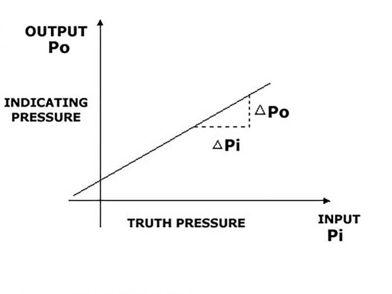
The diagram is a calibration diagram for a pressure gauge. What do you call the slope of the calibration curve?
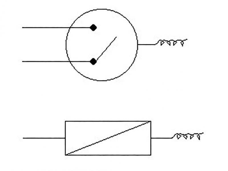
What is the difference between a THERMOSTAT and a TEMPERATURE TRANSMITTER, if any?
When you are calibrating an instrument what is the most common second step in the procedure (consult the manual)

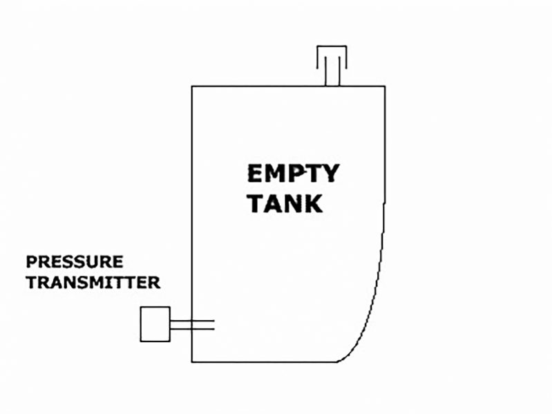
In a fresh water tank we are using a pressure transmitter with a range of 0-0.5 bar/4-20mA for level measurement.The transmitter is for different reasons installed 30 centimeters from the bottom of the tank,and the tank is 5 meters high. What will the output from the transmitter be when the tank is empty?
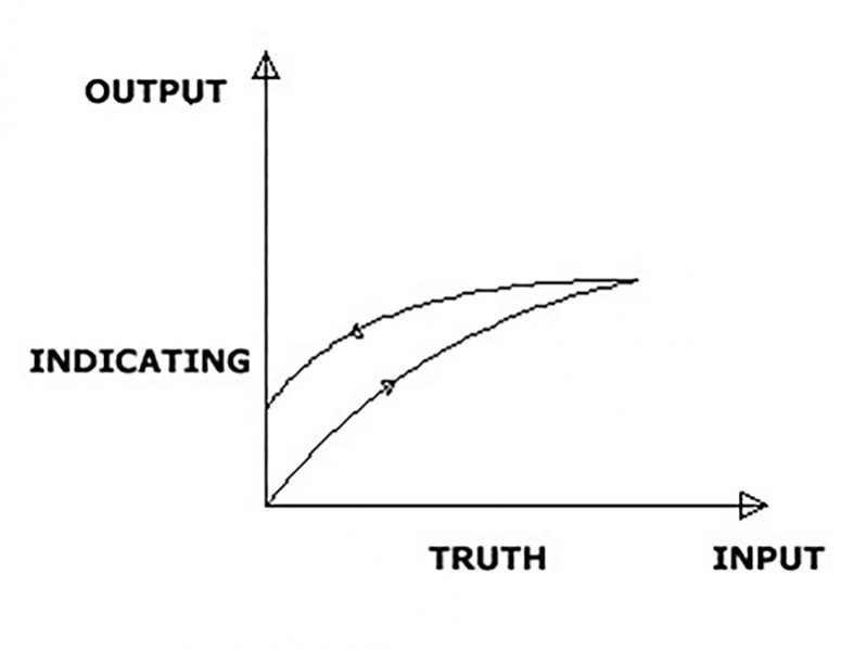
The pressure inlet to a pressure gauge is varied from zero to full scale and back to zero again. The output (indicating pressure) versus true pressure is shown in the diagr.The non - coincidence of loading and unloading curve is due to internal friction in the instrument. What do we call this phenomenon?
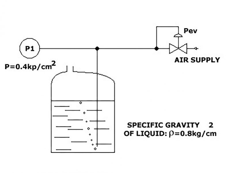
Liquid level in tanks is often measured by measuring the hydrostatic head or differential pressure. One method is the air bubble type which is illustrated here. Calculate the level in the tank, utilizing the figures given on the drawing.
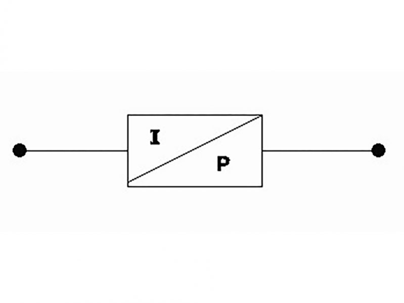
What is the most common signal from an I/P converter?
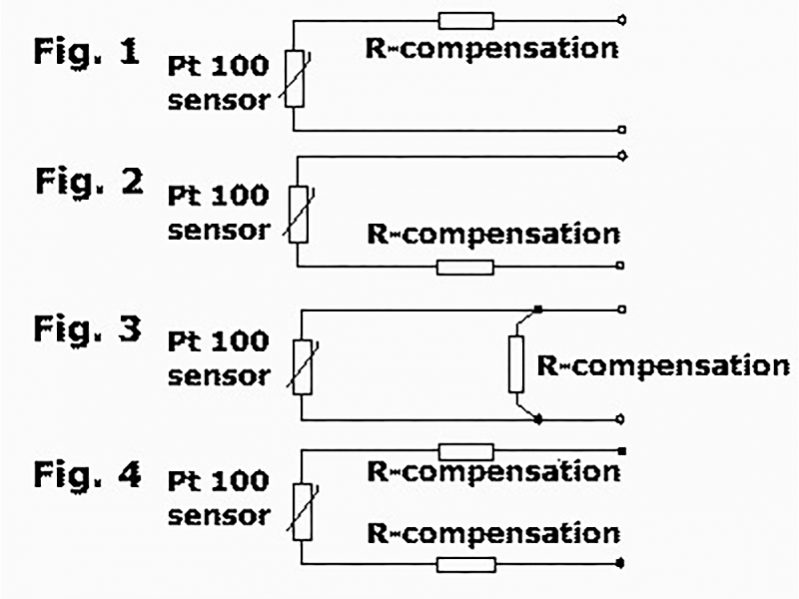
Due to the relative low resistance of a Pt 100 sensor we might have to compensate for the cable-resistance to ensure a correct reading. Which of the 4 alternatives given is correct for the connection of this compensation resistance.
The range of a transducer is 0-200 bar. The standard output signal is 4-20 mA. What is the output signal when the process value is 100 bar.

In what kind of measuring equipment can we find a Bourdon-tube?
Review Answers

